

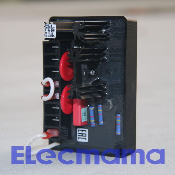


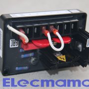
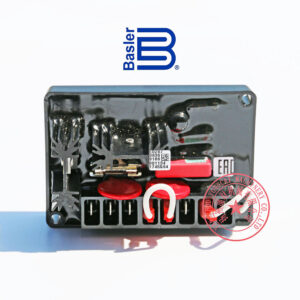
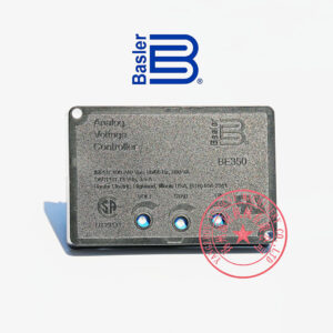
Marathon AVR BE350
Genuine Marathon Generator Spare Parts for you
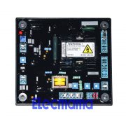
Part name : automatic voltage regulator (AVR)
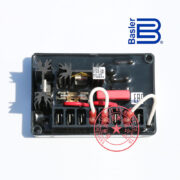
AVR brand : Basler
AVR model : BE350
Part number : 9166801134
Part application : Marathon Generator
AVR application : power generation
Manufacturer : Basler Electric
Country of origin : USA
Minimum Order Quantity (MOQ) : 1 piece
Recommended purchase quantity : 1-2 pieces
Packing material : strong carton
Net weight : 0.26 kg /pc
- Description
- Automatic Voltage Regulator (AVR)
- AVR model : BE350
- Part No. : 9166800143
- Manufacture : , USA company
Marathon Generator AVR BE350
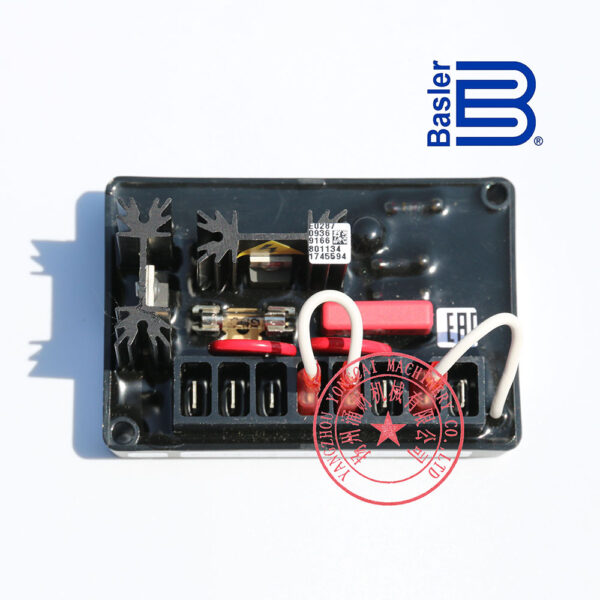
BE350 AVR for Marathon generator is manufactured by “Basler Electric” in USA.
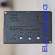
BASLER ELECTRIC BE350 is an analog voltage controller developed by Basler Electric Company in USA
The BE350 analog voltage controller regulates voltage on a 50 or 60 hertz brushless generator. Controller features include frequency compensation, solid-state buildup circuitry and EMI filtering.
UL recognized and CSA certified
INTRODUCTION
The BE350 analog voltage controller regulates voltage on a 50 or 60 hertz brushless generator. Controller features include frequency compensation, solid-state buildup circuitry, and EMI filtering.
SPECIFICATIONS
Output Power
Maximum Continuous: 3.5 Adc at 73 Vdc (255 W)
One-Minute Forcing: 5 Adc at 105 Vdc (525 W) with 240 Vac power input
Exciter Field DC Resistance
Minimum: 21 Ω
Input Power
Range: 190–240 Vac, ±10%, 1-phase
Frequency: 50/60 Hz, ±10%
Burden: 500 VA
Sensing Input
Common with ac power input: 190–240 Vac, single-phase, 50/60 Hz, ±10%
Fuse
Bussmann GDC-4A or equivalent
Rating: 4 Aac, 250 Vac
Type: Glass tube, 5 x 20 mm, time delayed
Voltage Adjustment Range
171 to 264 Vac
Regulation Accuracy
Better than ±1.0%, no-load to full-load
Response Time
Less than 1.5 cycles for ±5% change in sensing voltage
EMI Suppression
Internal electromagnetic interference (EMI) filtering
Voltage Buildup
Automatic voltage buildup occurs for residual generator voltages as low as 10 Vac.
Power Dissipation
8 W maximum
Temperature
Operating: –40 to 60°C (–40 to 140°F)
Storage: –65 to 85°C (–85 to 185°F)
Vibration
2 to 27 Hz: 1.3 G
27 to 52 Hz: 0.914 mm, double-amplitude
52 to 1000 Hz: 5 G
Shock
Withstands up to 20 G in each of three mutually perpendicular axes.
Weight
184 g (6.5 oz) net
Agency Certification
UL recognized and CSA certified
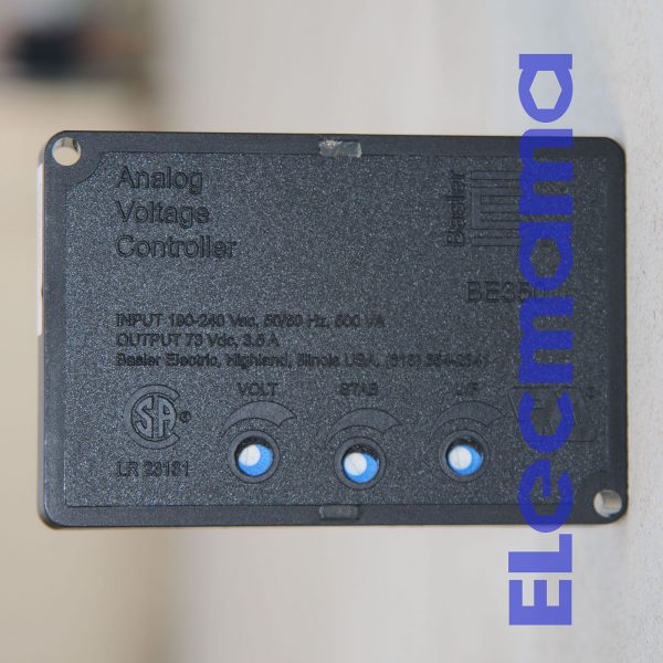
CONTROLS
BE350 controls consist of jumpers and screwdriver-adjusted potentiometers.
Potentiometer Controls
BE350 potentiometer controls are accessible through the controller front panel and are shown in Figure 1.
This control raises and lowers the generator output voltage.
VOLT Control
This control adjusts the stability by increasing and reducing the response time of the BE350.
STAB Control
This control adjusts the corner frequency point of the BE350 frequency compensation characteristic.
U/F Control
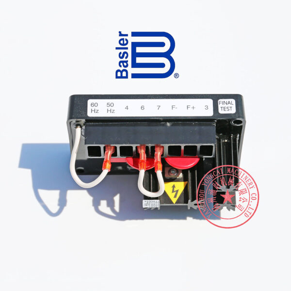
Jumpers
Two jumpers control BE350 operation: the Corner Frequency jumper and the Voltage Adjust Rheostat jumper. These jumpers are shown in Figure 2.
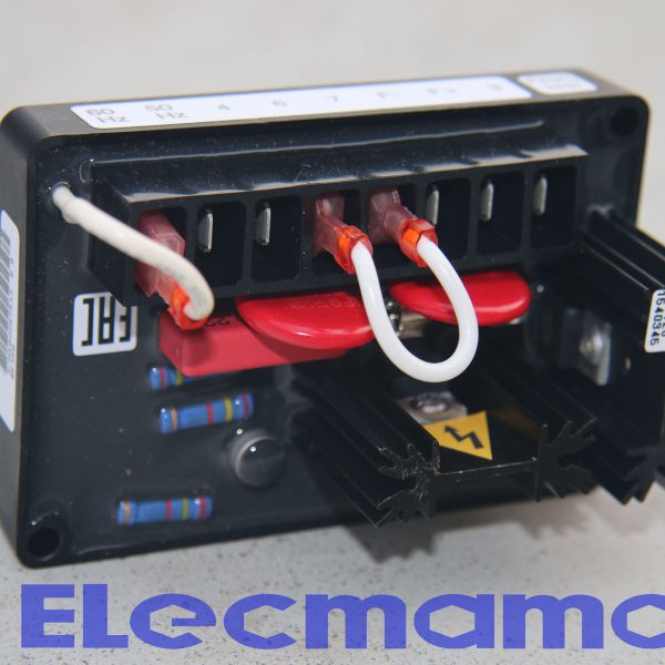
BE350 controllers are delivered with the Corner Frequency jumper set for 60 hertz operation. This gives a corner frequency of 55 hertz. For 50 hertz operation and a corner frequency of 45 hertz, the Corner Frequency jumper must be move to the 50 Hz terminal.
Corner Frequency Jumper
BE350 controllers are delivered with the Voltage Adjust Rheostat jumper connected across terminals 6 and 7. This enables adjustment of the generator output voltage through the controller’s internal Voltage Control potentiometer. Clockwise rotation of the Voltage Control potentiometer increases the generator voltage.
Voltage Adjust Rheostat Jumper
If remote adjustment of the generator output is desired, the Voltage Adjust Rheostat jumper must be replaced with a user-supplied rheostat. A 2000 ohm, ½ watt rheostat will provide adequate voltage adjustment for most applications. Figure 6 shows the proper remote rheostat connections.
INPUT POWER/SENSING INPUT
Power for the exciter field and BE350 is derived from the generator output. The acceptable power input range is 171 to 264 Vac. Connect the input power wiring to terminals 3 and 4 as shown in Figure 5.
EXCITER FIELD POWER CIRCUIT
Controller terminal F+ is connected to the brushless exciter field positive terminal and controller terminal F– is connected to the brushless exciter field negative terminal.
Related Products
 Read MoreQuick View
Landian AVR ZPWT-4B
 Read MoreQuick View
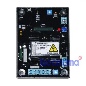
AVR SX460
AVR SX460 Automatic Voltage Regulator
Application : brushless generator
Country of origin : China
 Read MoreQuick View
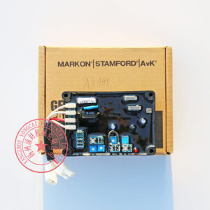
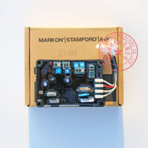
Stamford AVR AS480
Genuine Stamford Generator Spare Parts for you
Part name : automatic voltage regulator (AVR)
AVR brand : Stamford
AVR model : AS480
Part number : E000-14800
Part application : Stamford Generator
AVR application : power generation
Manufacturer : Cummins Generator Technologies Ltd.
Country of origin : UK
Minimum Order Quantity (MOQ) : 1 piece
Recommended purchase quantity : 1-2 pieces
Packing material : strong carton
Net weight : 0.36 kg /pc
 Read MoreQuick View
AVR SX440
AVR SX440 Automatic Voltage Regulator
Application : brushless generator
Country of origin : China
 Read MoreQuick View
Basler AVR BE350
Genuine Marathon Generator Spare Parts for you
Part name : automatic voltage regulator (AVR)
AVR brand : Basler
AVR model : BE350
Part number : 9166801134
Part application : Marathon Generator
AVR application : power generation
Manufacturer : Basler Electric
Country of origin : USA
Minimum Order Quantity (MOQ) : 1 piece
Recommended purchase quantity : 1-2 pieces
Packing material : strong carton
Net weight : 0.26 kg /pc